
IBM PC AT (5170) Hard Disk Replacement

The IBM PC AT (5170) was sold with a 20 MB or 30 MB fixed disk running on IBM's Fixed Disk and Diskette Drive Adapter, which carries both the hard disk and the diskette controllers.[1] The first drive IBM fitted, the 20 MB CMI 6426-S, had a very high failure rate, and IBM moved to the Seagate ST-4026; the Model 239 of October 1985 has a 30 MB drive made by IBM.[2] IBM's FRU numbers are 6278099 for the 20 MB drive and 8286216 for the 30 MB drive, with keeper bar 6489949, signal cable 8286124 and data cable 8286129.[3]
Replacing a failed drive with another MFM drive on the IBM adapter means removing the old drive, setting the new drive's jumpers and terminator to suit the cable, entering its type number in SETUP, low-level formatting it with IBM's Advanced Diagnostics, and then partitioning and formatting it under DOS. The cabling details here are for a single drive, as in minuszerodegrees' diagrams.[4]
Symptoms
[edit | edit source]The POST tests a fixed disk set up in SETUP and reports:[5]
- 1782: the controller failed its own diagnostic or did not answer.
- 1780 (1781 for drive D): the controller passed but the drive did not recalibrate.
- 1790 (1791 for drive D): the drive recalibrated but a read failed.
Each has causes other than a dead drive, among them a cable on the wrong connector, a wrong drive-select jumper or a wrong SETUP type; they are listed under fixed disk faults in the troubleshooting guide. Check those first. IBM's own advice before replacing a failing drive is to try formatting it with the Advanced Diagnostics, as in the low-level format below.[6]
Safety and data
[edit | edit source]- Unplug the power cord before removing the cover.[7]
- Hold the drive by its frame. IBM warns not to lift it by the printed circuit board.[8]
- IBM warns that normal shipping and handling can lose all data and formatting on the drive. Back up anything still readable, and run "Prepare System for Moving" from the Advanced Diagnostics before taking a working drive out.[8]
- A low-level format, a surface analysis and FDISK all destroy the data on the drive.[6][9]
Tools and parts
[edit | edit source]- A screwdriver for the cover screws, the drive mounting screws and clips or keeper bar.[8]
- IBM's Advanced Diagnostics for IBM Personal Computer AT diskette. Minuszerodegrees points out that the low-level format is on the Advanced diagnostics diskette, not on the plain Diagnostics for the IBM Personal Computer AT diskette.[10]
- A DOS boot diskette with FDISK and FORMAT.[9]
- The replacement drive's defect list, which is printed on the drive, if an unconditional format is used.[10][6]
- A replacement MFM drive whose geometry matches one of the drive types in the AT's BIOS. Drives IBM fitted carry their type number on a sticker on the front.[11]
| Drive | IBM type | Notes |
|---|---|---|
| CMI 6426 | 2 | MFM |
| Seagate ST-4026 | 2 | MFM |
| IBM 0665-30 | 2 | MFM; about 20 MB formatted |
| Seagate ST-4038 | 20 | MFM |
| IBM 0665-38 | 20 | MFM; about 30 MB formatted |
| IBM 0665-53 | 21 | MFM; about 43 MB formatted |
For any other drive, find its cylinders, heads, sectors per track (assume 17 if not given) and write precompensation cylinder, and match them against the type table for the BIOS fitted. Types 1 to 14 exist in all three BIOS revisions; types 16 to 22 need the 06/10/85 or 11/15/85 BIOS; type 23 needs 11/15/85; type 15 must not be used.[11][12] IBM's 30 MB drives are type 20, which needs the 06/10/85 BIOS or later; IBM's 30 MB upgrade kit for type 1 machines came with 06/10/85 ROMs for this reason.[13][14]
Procedure
[edit | edit source]Before removing the old drive
[edit | edit source]- If the drive still works, back it up.[8]
- Boot the Advanced Diagnostics diskette and choose option 3, PREPARE SYSTEM FOR MOVING, from the Select an Option menu.[8][15]
- Switch off and remove the cover as described in the battery replacement guide.[7]
Removing the drive
[edit | edit source]
IBM's procedure:[8]
- Remove the mounting screws and clips. On drive C a keeper bar may be fitted instead of the clips.
- If the system has two fixed disks and one diskette drive, the diskette drive may have to come out first to reach the second fixed disk's connectors.
- Disconnect the ground wire from the drive.
- Disconnect the power cable.
- Disconnect the signal (control) cable.
- Disconnect the data cable.
- Grasp the drive by its frame and slide it forward out of the system unit.
Setting up the replacement drive
[edit | edit source]
- Check the adapter's jumpers. The IBM BIOS expects the hard disk controller at its primary address (jumper E5 to E6, 1F0h) and the diskette controller at its primary address (E2 to E3, 3F0h); these are the factory settings. Leave E7/E8 and E11/E12 alone: they are factory jumpers.[16]
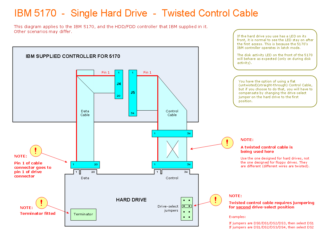
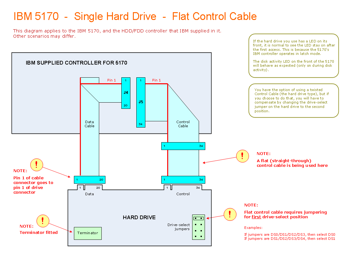
- Work out which control cable you have. IBM's cable set for the 5170 has a twisted control cable for the hard drive. A hard drive twisted cable is not the same as a floppy drive twisted cable: different conductors are twisted.[4]
- Set the drive-select jumper on the drive. With IBM's twisted control cable, use the second position: DS1 on a drive whose jumpers are numbered DS0 to DS3, or DS2 on a drive numbered DS1 to DS4. With a flat (straight-through) control cable, use the first position: DS0 or DS1 respectively.[17][18]
- Fit the terminator on the drive.[17][18]

Fitting the drive
[edit | edit source]
IBM's replacement procedure is the removal procedure reversed.[19]
- Slide the drive into the bay, holding it by its frame.[8]
- Connect the 20-pin data cable from J4 on the adapter (J4 serves drive C) and the 34-pin control cable from J5, with pin 1 of each cable connector on pin 1 of the drive's connector.[17][5]
- Connect the power cable and the ground wire.[8]
- Refit the clips or keeper bar and the mounting screws, refit the diskette drive if it was removed, and refit the cover.[8][20]
IBM's drawing of the fixed disk data cable is marked "Do not remove tape" where the cable is folded.[21]
Setting the drive type
[edit | edit source]Run SETUP and enter the drive's type number. SETUP is on IBM's diagnostics diskettes, and minuszerodegrees also gives ways of running it without the diskette; see the battery replacement guide.[22] The low-level format assumes that the type has already been set correctly.[9]
Low-level format
[edit | edit source]Minuszerodegrees' procedure with version 2.07 of the Advanced Diagnostics for IBM Personal Computer AT diskette, for one hard drive. Allow an hour.[10]
- Boot the 5170 from the diskette.
- Enter 0 for SYSTEM CHECKOUT, and wait a minute or more for the next menu.
- Enter Y to confirm that the list of installed devices is correct.
- Enter 0 for RUN TESTS ONE TIME.
- Enter 17 for the fixed disk.
- Enter
7,cfor the FORMAT MENU on drive C. - Optionally change the interleave: enter 4 (CHANGE INTERLEAVE), Y to confirm, then 2 for 2:1, and press Enter. Minuszerodegrees finds IBM's default of 3:1 too conservative and 2:1 faster. IBM's menu accepts 2:1 to 8:1 and warns that changing the interleave can change system performance drastically.[6]
- Enter
1,cfor a conditional format, or2,cfor an unconditional one. A conditional format scans for tracks already marked defective, formats, and then runs a surface analysis. An unconditional format asks for the defect list printed on the drive and does no surface test, so run SURFACE ANALYSIS (option 3) afterwards. - Wait. During the last stage of the surface analysis, when defective tracks are being marked, the program can look as if it has stopped.
IBM's own steps for the same format are in the Hardware Maintenance Reference, including the prompts about printing the defect list on LPT1 and confirming before the format starts.[6]
Partitioning and formatting under DOS
[edit | edit source]Boot from a DOS diskette and run the standard FDISK and FORMAT operations.[9] IBM notes that its diagnostics format is not the operating system format, and that the drive must also be formatted with the operating system before files are restored to it.[6] If DOS 3.3 gives "Disk Boot failure" after FDISK and FORMAT, minuszerodegrees suggests a later DOS, such as 6.22: early versions do not cope with some areas of the drive being unusable.[9]
Testing
[edit | edit source]- The POST completes without a 1780, 1781, 1782, 1790 or 1791 error.[5]
- In the Advanced Diagnostics, the fixed disk menu's RUN ALL TESTS (option 5) runs the write/read/compare, seek, head select and error-correction tests, and READ VERIFY (option 6) reads the whole drive and reports unreadable tracks.[23]
- A drive LED that stays on after the first access is normal with IBM's adapter, which runs the drive in latch mode. The AT's own disk activity light on the front panel lights only during disk activity.[17]
Revision notes
[edit | edit source]- IBM states that all AT fixed disks made after 1 October 1985, except the 20 MB drive, carry an identifying label.[3]
- With the 06/10/85 and 11/15/85 BIOS, a third-party hard disk controller in place of IBM's adapter can cause a 601 at POST; see the main IBM PC AT page.[14]
- Controllers with their own BIOS ROM, such as SCSI and XT-IDE cards, usually ignore the SETUP drive type.[24]
Related pages
[edit | edit source]- IBM PC AT (5170)
- IBM PC AT Maintenance Guide
- IBM PC AT Troubleshooting Guide
- IBM PC AT (5170) Battery Replacement
- Hard Drive Maintenance and Repair
References
[edit | edit source]- ↑ IBM, IBM Personal Computer Family Service Information Manual, SA38-0037-00 (July 1989), Chapter 9 "5170 Personal Computer AT", pp. 9-1 to 9-2: the 20 MB or 30 MB fixed disk on the Fixed Disk and Diskette Drive Adapter. Hosted as File:IBM Personal Computer Family Service Information Manual SA38-0037-00.pdf, described at IBM Personal Computer Family Service Information Manual.
- ↑ Minuszerodegrees.net, "IBM 5170 – Failures of the CMI 6426 Hard Drive".
- ↑ 3.0 3.1 IBM, Hardware Maintenance Service, 6280087, Revised Edition (March 1986), "Parts (AT)", Assembly 4 "Fixed Disk Drives", p. 11: FRU numbers and the identifying-label note. Hosted as File:IBM Hardware Maintenance Service 6280087 Parts Catalog (AT).pdf.
- ↑ 4.0 4.1 Minuszerodegrees.net, "IBM 5170 Fixed Disk and Diskette Drive Adapter – Cabling Information": flat and twisted control cables, IBM's supplied twisted cable, and the difference between floppy and hard drive twisted cables.
- ↑ 5.0 5.1 5.2 Minuszerodegrees.net, "IBM 5170 – POST – Some errors (on-screen, and otherwise)": errors 1780 to 1791 and their causes, including the data cable on J4 for drive C.
- ↑ 6.0 6.1 6.2 6.3 6.4 6.5 IBM, Hardware Maintenance Reference, 6280088 (1986), Introduction to Diagnostics (AT), "Format the Fixed Disk Drive", p. 2-21, and "Formatting a Fixed Disk Drive", pp. 2-22 and 2-23: the format options, interleave range and warning, the defect prompts, and the advice to try formatting before replacing a failing drive.
- ↑ 7.0 7.1 IBM, Hardware Maintenance Reference, 6280088 (1986), Repair Information (AT), "Cover 1005", pp. 3-27 and 3-28. Hosted as File:IBM Hardware Maintenance Reference 6280088 Repair Information (AT).pdf.
- ↑ 8.0 8.1 8.2 8.3 8.4 8.5 8.6 8.7 8.8 IBM, Hardware Maintenance Reference, 6280088 (1986), Repair Information (AT), "Fixed Disk Drive 1045", pp. 3-34 and 3-35: the data warning, Prepare System for Moving, the removal steps, the keeper bar and the warning not to lift the drive by its circuit board.
- ↑ 9.0 9.1 9.2 9.3 9.4 Minuszerodegrees.net, "IBM 5170 – Low-Level Format for Supplied Controller": the format assumes the SETUP type is set, the FDISK/FORMAT follow-up and the DOS 3.3 note.
- ↑ 10.0 10.1 10.2 Minuszerodegrees.net, "Using the IBM 'Advanced Diagnostics for IBM AT' Disk to Low-Level Format a Hard Drive in an IBM 5170", one page, version 2.07 of the diskette.
- ↑ 11.0 11.1 11.2 Minuszerodegrees.net, "IBM 5170 – Determining the Hard Drive Type Number": the type sticker, known drives, and matching a drive's geometry to the type table.
- ↑ Minuszerodegrees.net, "IBM 5170 – Hard Drive Support In BIOS": types 1 to 23 and the BIOS revisions that support each.
- ↑ IBM, IBM Personal Computer Family Service Information Manual, SA38-0037-00, Chapter 9, p. 9-7: IBM's 20 MB drives are type 2 and 30 MB drives type 20; type 20 needs diagnostics at level 2.0 or later and a BIOS that supports it.
- ↑ 14.0 14.1 Minuszerodegrees.net, "IBM 5170 – BIOS Revisions": the 30 MB upgrade kit with 06/10/85 ROMs, and the 601 error with third-party controllers.
- ↑ Minuszerodegrees.net, "IBM 5170 Fixed Disk and Diskette Drive Adapter – Jumper Information", first and second generation adapters.
- ↑ 17.0 17.1 17.2 17.3 Minuszerodegrees.net, "IBM 5170 – Single Hard Drive – Twisted Control Cable", cabling diagram.
- ↑ 18.0 18.1 Minuszerodegrees.net, "IBM 5170 – Single Hard Drive – Flat Control Cable", cabling diagram.
- ↑ IBM, Hardware Maintenance Reference, 6280088 (1986), Repair Information (AT), "How to Use the Repair Information", p. 3-3: replace a FRU by reversing the removal procedure.
- ↑ IBM, Hardware Maintenance and Service, IBM Personal Computer AT, 1502242 (March 1984), Volume 2, "Cover Replacement 1006", p. 5-9. Scan via minuszerodegrees.net.
- ↑ IBM, Hardware Maintenance Reference, 6280088 (1986), Repair Information (AT), "Fixed Disk Drive Cable", p. 3-16.
- ↑ Minuszerodegrees.net, "IBM 5170 – SETUP Procedure".
- ↑ IBM, Hardware Maintenance Reference, 6280088 (1986), Introduction to Diagnostics (AT), "Fixed Disk Drive and Adapter", pp. 2-19 and 2-20.
- ↑ Minuszerodegrees.net, "IBM 5170 – Basics, for 5170 beginners".