

Magnavox Odyssey 2000
 | |
| An Odyssey 2000, with one knob for each player | |
| Specifications | |
|---|---|
| Manufacturer | Magnavox Consumer Electronics Company |
| Type | Dedicated home video game console |
| Released | 1977[1][2] |
| CPU | None; one game chip, Magnavox IC1 612114 (General Instrument AY-3-8500)[3][1][4] |
| Memory | None |
| Storage | — |
| Display | Black and white, RF output on VHF channel 3 or 4[5][6] |
| Sound | Built-in speaker; no on/off switch[6][3] |
| Power | Six C cells or a 9 V AC adaptor[6] |
| OS / Firmware | — |
| Predecessor | Magnavox Odyssey 300 |
| Successor | Magnavox Odyssey 3000 |
| Model no. | BH7510[6] |
The Magnavox Odyssey 2000 (model BH7510) is a dedicated home video game console made by Magnavox from 1977. It plays Smash, Tennis and Hockey for two players, and a one-player Practice game, in black and white, with on-screen scores, an automatic serve and two skill levels; each player has a single knob that moves the player up and down.[6][7][1] It is built around the same General Instrument AY-3-8500 game chip as the Magnavox Odyssey 300, which Magnavox lists as IC1, part 612114-1 on both consoles.[1][3][8]
History
[edit | edit source]Pong-Story describes the Odyssey 2000 as the Odyssey 300 with a fourth game, one of three consoles Magnavox released in 1977 with General Instrument chips, alongside the Magnavox Odyssey 3000 and Magnavox Odyssey 4000.[2] Magnavox's service manual for the BH7510 was issued in October 1977 by the Magnavox Consumer Electronics Company.[6] Philips sold the console in Europe as the Philips Odyssey 2000, with a PAL version of the game chip, a European television lead and a Philips label; Wikipedia says it replaced the Philips Odyssey 200 in 1977.[2][1] A Philips Odyssey 2000 bought in Italy, type G 7509/00, is marked as made in the USA. It has the same case and games as the Magnavox console but no socket for an external power supply, so it runs from its six C cells only.[9]
Hardware
[edit | edit source]Circuit
[edit | edit source]The main board carries IC1 and three transistors: Q1, the voltage regulator for IC1; Q2, the 2 MHz oscillator that clocks IC1 through pin 17; and Q3, the sound amplifier. Unlike the Odyssey 300, the RF stage is a separate shielded module, the RF modulator assembly 703938, fed from the main board through terminals W10 (supply) and W11 (video). The Odyssey 300 has its RF oscillator, Q4, on the main board.[10][3][8] Magnavox's board drawing marks the board 211077-5 and 703837; the Odyssey 300 board is 211077-1.[11] A photograph of a Philips Odyssey 2000 board marked 703837 shows IC1 marked AY-3-8500, the only integrated circuit on the board.[4][9] Magnavox's board drawing says the screening is reversed for the skill switch S2 and the game switch S3 and refers the reader to the schematic; José Antonio Ortigueira found the SKILL and GAME SELECT legends on his board the other way round from the panel on the case.[11][9]
| Ref | Function (schematic) | Magnavox part |
|---|---|---|
| IC1 | Game chip | 612114-1 |
| Q1 | Voltage regulator | 610224-1 |
| Q2 | 2 MHz oscillator | 610139-3 |
| Q3 | Sound amplifier | 610232-2 |
| Z1 | 7 V zener diode for the regulator | 530073-1039 |
| Q1 (RF module) | RF oscillator | 610139-2 |
Power
[edit | edit source]The console runs from six C cells in a battery holder or a 9 V AC adaptor that plugs into a socket at the top back of the case. Magnavox's booklet advises taking the cells out if the console is normally run from the adaptor, to prevent damage from leaking cells.[6][7] Q1 drops the 9 V supply to 6.4 V for IC1 pin 4, with its base held at 7 V by the zener Z1. The RF module takes its supply through R5, a 1500 Ω half-watt resistor.[10]
Controls
[edit | edit source]The centre panel has the GAME switch (Smash, Tennis, Hockey), the SKILL switch (Practice, Pro, Amateur) and the three-position POWER/RESET switch: off, on, and a spring-loaded reset that clears the score.[7][3] Each player's knob is a 500 kΩ control, R10 for the left ("visiting team") player and R8 for the right ("home team") player.[3][11] The channel switch is on the RF module, above the main board.[7][3] There is no sound switch.[6]
| Position | Setting | Ball speed | Player size | Deflection angles |
|---|---|---|---|---|
| Bottom | Amateur | Slow | Small | Four |
| Centre | Pro | Fast | Large | Four |
| Top | Practice | One-player practice game; the left player control does not work | ||
In Practice the player defends against the ball alone, and each miss adds a point; the game ends at 15.[7]
Scoring and serve
[edit | edit source]The score is shown on screen. The ball is served automatically from the side that won the previous point, and after either side reaches 15 points the ball keeps being served but neither player can return it, until the game is reset.[6][7] A different tone sounds for a hit on a player, a hit on a wall and a point.[6]
Troubleshooting
[edit | edit source]Magnavox's service manual has no symptom chart. It gives a voltage chart for IC1, transistor voltages on the schematic and two adjustments: the 2 MHz oscillator and the channel 3 and 4 RF oscillator. Symptoms and checks are on Magnavox Odyssey 2000 Troubleshooting Guide, the adjustments on Magnavox Odyssey 2000 General Maintenance and the three electrolytic capacitors on Magnavox Odyssey 2000 Capacitor Replacement Guide.[6][10]
Documentation
[edit | edit source]Magnavox Service Manual No. 6507 for the BH7510 and the Odyssey 2000 instruction booklet IB 3270-1 are hosted on the wiki and described on Magnavox Odyssey 2000 Documentation.[6][7]
Gallery
[edit | edit source]-
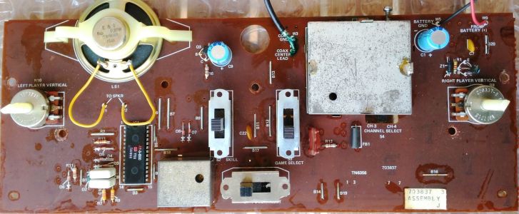 Main board of a Philips Odyssey 2000, the European version, board 703837
-
 A Philips Odyssey 2000 opened, with the board, RF module, speaker and battery holder
-
 Magnavox's drawing of the main board (Service Manual No. 6507, pp. 6507-5 and 6507-6)


Related pages
[edit | edit source]- Magnavox Odyssey 2000 General Maintenance
- Magnavox Odyssey 2000 Troubleshooting Guide
- Magnavox Odyssey 2000 Capacitor Replacement Guide
- Magnavox Odyssey 2000 Documentation
- Magnavox Odyssey 300, the three-game model it followed
- Magnavox Odyssey 3000
References
[edit | edit source]- ↑ 1.0 1.1 1.2 1.3 1.4 Wikipedia, "Magnavox Odyssey series" (retrieved 2026-10-19), sections on the Odyssey 2000 and the Philips Odyssey 2000: model BH7510, 1977 release, the AY-3-8500, the single knob per player, the Practice game, 15-point games, power, and the Philips version replacing the Philips Odyssey 200 in 1977.
- ↑ 2.0 2.1 2.2 David Winter, Pong-Story, "Other Magnavox Odyssey systems" (retrieved 2026-10-19): the Odyssey 2000, 3000 and 4000 of 1977 with General Instrument chips, the Odyssey 2000 as the Odyssey 300 with a fourth game, and the Philips Odyssey 2000 as a direct copy with a PAL game chip, a European television lead and a Philips label.
- ↑ 3.0 3.1 3.2 3.3 3.4 3.5 3.6 3.7 Magnavox, Service Manual No. 6507, October 1977, p. 6507-2: BH7510 replacement parts list and RF modulator replacement parts list (coils, capacitors with type, value, rating and part number, switches, semiconductors, miscellaneous). Hosted as File:Magnavox Odyssey 2000 Service Manual 6507.pdf.
- ↑ 4.0 4.1 José Antonio Ortigueira Amor, photograph of the main board of a Philips Odyssey 2000, 26 November 2020, on Wikimedia Commons as File:Philips Odyssey 2000 placa 2a.jpg (CC BY 4.0; retrieved 2026-10-19): board 703837 with IC1 marked AY-3-8500. Hosted as File:Philips Odyssey 2000 main board.jpg.
- ↑ Nerdly Pleasures, "Sears (Atari) Tele-games Pong vs Magavox Odyssey 100 - Battle of the First Pong Consoles", 7 August 2022 (retrieved 2026-10-19): the later Odyssey models, with the 300, 2000 and 3000 in black and white; and the faults the author fixed on an Odyssey 100 (a noisy channel switch, dirty power and ball reset switch contacts, a broken battery holder contact). Owner's hands-on report.
- ↑ 6.00 6.01 6.02 6.03 6.04 6.05 6.06 6.07 6.08 6.09 6.10 6.11 Magnavox Consumer Electronics Company, Service Manual No. 6507: BH7510 Odyssey, first issue, October 1977, p. 6507-1: general information (6 C cells or an optional AC to DC 9 V adaptor; Smash, Tennis, Hockey and Practice; amateur and pro skill levels; on-screen scoring, automatic serve, 15-point game; no provision to turn the sound off), the service adjustments (2 MHz oscillator; channel 3 and 4 RF oscillator) and typical operation. Hosted as File:Magnavox Odyssey 2000 Service Manual 6507.pdf.
- ↑ 7.0 7.1 7.2 7.3 7.4 7.5 7.6 7.7 The Magnavox Company, Odyssey 2000 Installation and Game Rules, IB 3270-1, 1977: the notice on screen burn and the introduction (p. 2), the antenna-game switch and game cord (pp. 3 and 4), battery installation and the channel switch (p. 5), the control panel (p. 6), the power/reset, game and skill switches and the player control (p. 7), Smash, Tennis and Hockey (pp. 8 to 10), Practice (p. 11). Hosted as File:Magnavox Odyssey 2000 Installation and Game Rules IB3270-1.pdf.
- ↑ 8.0 8.1 Magnavox, Service Manual No. 6504: BG7500 Odyssey (Odyssey 300), October 1976, p. 6504-2: BG7500 replacement parts list, with IC1 612114-1 and the switch part numbers. Hosted as File:Magnavox Odyssey 300 Service Manual 6504.pdf.
- ↑ 9.0 9.1 9.2 José Antonio Ortigueira Amor, Retro Ordenadores Orty, "Consolas Magnavox, Philips y Phonola", section "Philips Odyssey 2000 (modelo G 7509/00) (versión PAL) (1977)", in Spanish (retrieved 2026-10-19): the owner's Italian-market console, type G 7509/00, made in the USA, with the same case and games as the Magnavox Odyssey 2000 and no socket for an external power supply; the bottom case removed by turning the central screw, exposing the solder side of the board, with the board and battery compartment fixed to the top case; the channel switch beside the modulator; five screws holding the board; the AY-3-8500 as the only IC; the SKILL and GAME SELECT legends on the board the other way round from the case top. Owner's hands-on description.
- ↑ 10.0 10.1 10.2 10.3 Magnavox, Service Manual No. 6507, October 1977, pp. 6507-3 and 6507-4: BH7510 schematic diagram with the transistor voltages, the IC1 voltage chart and its notes 1 to 9, the RF modulator assembly 703938 schematic and board drawing, and the antenna switch box. Hosted as File:Magnavox Odyssey 2000 Service Manual 6507.pdf.
- ↑ 11.0 11.1 11.2 Magnavox, Service Manual No. 6507, October 1977, pp. 6507-5 and 6507-6: main P.C. board viewed from the component side (marked 211077-5 and 703837), a drawing of the console's controls, and the cabinet and antenna/game switch replacement parts lists. Hosted as File:Magnavox Odyssey 2000 Service Manual 6507.pdf.
