

Magnavox Odyssey Documentation
Magnavox's service documentation for the Magnavox Odyssey (model 1TL200) is Service Manual No. 6500, which covers the 1TL200BLAK and 1TL200BK12.
Service Manual No. 6500
[edit | edit source]Magnavox Service Manual No. 6500, 1TL200 BLAK & BK12 Odyssey Game Simulator, is The Magnavox Company's 16-page service manual for the two United States versions of the Odyssey. It is filed in the 1974 "D" Series (Volume 11), Miscellaneous Section; this copy is the second issue, May 1975, code DMFWP274, copyright 1975.[1] The scan is Sylvain De Chantal's 600 dpi copy from the Internet Archive, reduced to 300 dpi for hosting.[2]
Contents
[edit | edit source]| Page | Contents |
|---|---|
| 6500-1 | Photograph of the set; Figure 1, Odyssey block diagram; general description |
| 6500-2 | Figure 2, set-up with the rifle; installation instructions; 300 Ω and 75 Ω antenna connections; 701517-1 antenna-game switch box parts list |
| 6500-3 | Checkout procedure; circuit modules replacement parts list |
| 6500-4 | Replacement parts lists: 701578-1 and -4 player control, game box (cards, overlays and accessories), 703490-4 and -5 master board |
| 6500-5 | Master control unit servicing; 701477-3 and -5 master control parts list; service adjustments, vertical and horizontal frequency |
| 6500-6 | Master board reference guide (top view); Table 1, spot sizes; spot size adjustments |
| 6500-7 | Figure 3, master board module location |
| 6500-8 to 6500-10 | 1TL200 BLAK schematic diagram (master PC board 703490-4), with the game card interconnections for cards 1 to 10, production run component tables, the external power jack and the Rifletronix board |
| 6500-11 to 6500-13 | 1TL200BK12 schematic diagram (master PC board 703490-5), with the interconnections for cards 1 to 12 |
| 6500-14 | Odyssey troubleshooting: supply checks and 13 symptoms |
| 6500-15 | 1TL950 rifle accessory servicing: sight alignment, LDR bias adjustment, rifle troubleshooting |
| 6500-16 | Rifle drawings, 1TL950 rifle schematic diagram, 703520-1 Rifletronix board parts list |
The schematic diagrams are fold-out sheets, scanned in overlapping parts, so pages 6500-8 to 6500-13 appear on six PDF pages with some overlap. Outside the schematics, the PDF page numbers match the manual's page numbers.[2]
What it does not contain
[edit | edit source]- No case disassembly instructions. Servicing is described at the level of adjustments and plug-in modules.[3]
- No parts lists for the inside of the modules; Magnavox notes that individual parts within a module were not available. The module circuits, with component values, are on the schematics.[4][5]
- No capacitor or resistor positions on the master board drawing, which shows the module sockets, adjustment controls, test points and connectors only.[6]
- Nothing on the later 1TL200BK13, the 1TL200BL99 renewal units or the export models such as the YE7100.[1][7]
What it settles
[edit | edit source]- The regulated supply at TP1: +5.6 V on the 1TL200BLAK and +6.2 V on the 1TL200BK12; replace the batteries if W1 is below 7.5 V.[8]
- The sync frequencies: 60 Hz ± 1 Hz at TP2 (R39) and 15,734 Hz ± 50 Hz at TP3 (R38).[3]
- Every electrolytic capacitor value on the master board and rifle board, with Magnavox part numbers, and the two in the horizontal sync generator module.[9][10][5]
- The module part numbers for each version.[4]
Pages that cite this document
[edit | edit source]- Magnavox Odyssey: models, modules, power, the BLAK and BK12 differences.
- Magnavox Odyssey General Maintenance: supply checks, module handling, the frequency and spot size adjustments, the rifle adjustments.
- Magnavox Odyssey Troubleshooting Guide: the checkout procedure, test points and the symptom chart.
- Magnavox Odyssey Capacitor Replacement Guide: capacitor values, ratings and part numbers.
Download: Magnavox Odyssey 1TL200 Service Manual 6500.pdf
Figures rendered from the manual
[edit | edit source]-
 Master board reference guide (p. 6500-6)
-
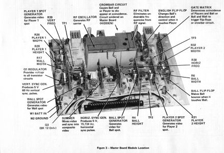 Figure 3, master board module location (p. 6500-7)


References
[edit | edit source]- ↑ 1.0 1.1 1.2 The Magnavox Company, Service Manual No. 6500: 1TL200 BLAK & BK12 Odyssey Game Simulator, second issue, May 1975, p. 6500-1: general description, the Master Control Unit with a master board and 12 solid-state plug-in modules, Figure 1 block diagram. Hosted as File:Magnavox Odyssey 1TL200 Service Manual 6500.pdf.
- ↑ 2.0 2.1 2.2 Internet Archive, "Magnavox Odyssey series Service Manuals & Game Manuals", uploaded 28 January 2018 by Sylvain (Sly DC) De Chantal; file "Magnavox Odyssey 1TL200 BLAK & BK12 Service Manual.pdf", 16 pages scanned at 600 dpi, page 1 marked "Scanned by Sly DC (2018)" (retrieved 2026-10-19).
- ↑ 3.0 3.1 The Magnavox Company, Service Manual No. 6500: 1TL200 BLAK & BK12 Odyssey Game Simulator, May 1975, p. 6500-5: master control unit servicing, the 701477-3 and -5 master control parts list, removing modules, the caution on the RF oscillator and RF filter, and the vertical and horizontal frequency adjustments. Hosted as File:Magnavox Odyssey 1TL200 Service Manual 6500.pdf.
- ↑ 4.0 4.1 The Magnavox Company, Service Manual No. 6500: 1TL200 BLAK & BK12 Odyssey Game Simulator, May 1975, p. 6500-3: checkout procedure, steps 1 to 5, and the circuit modules replacement parts list ("individual parts with the module are not available"). Hosted as File:Magnavox Odyssey 1TL200 Service Manual 6500.pdf.
- ↑ 5.0 5.1 The Magnavox Company, Service Manual No. 6500: 1TL200 BLAK & BK12 Odyssey Game Simulator, May 1975, pp. 6500-8 to 6500-13: 1TL200 BLAK schematic diagram (master PC board 703490-4) and 1TL200BK12 schematic diagram (master PC board 703490-5), with the game card interconnections, the regulator and crowbar circuit, the module circuits and the J1 external power jack. Hosted as File:Magnavox Odyssey 1TL200 Service Manual 6500.pdf.
- ↑ The Magnavox Company, Service Manual No. 6500: 1TL200 BLAK & BK12 Odyssey Game Simulator, May 1975, p. 6500-6: master board reference guide (top view), Table 1 spot sizes and the spot size adjustments. Hosted as File:Magnavox Odyssey 1TL200 Service Manual 6500.pdf.
- ↑ David Winter, Pong-Story, "Magnavox Odyssey, the first video game system" (retrieved 2026-10-19): development at Magnavox, the 1TL200 production table (models, runs, years), the model, serial and run labels, the contents of the box, technology (about 40 transistors and 40 diodes, cartridges as jumper sets), price, production and sales figures, exports and clones.
- ↑ The Magnavox Company, Service Manual No. 6500: 1TL200 BLAK & BK12 Odyssey Game Simulator, May 1975, p. 6500-14: Odyssey troubleshooting, the supply checks at TP1 and W1, interchangeable modules, and symptoms 1 to 13. Hosted as File:Magnavox Odyssey 1TL200 Service Manual 6500.pdf.
- ↑ The Magnavox Company, Service Manual No. 6500: 1TL200 BLAK & BK12 Odyssey Game Simulator, May 1975, p. 6500-4: replacement parts lists for the 701578-1 and -4 player control, the game box, and the 703490-4 and -5 master board. Hosted as File:Magnavox Odyssey 1TL200 Service Manual 6500.pdf.
- ↑ The Magnavox Company, Service Manual No. 6500: 1TL200 BLAK & BK12 Odyssey Game Simulator, May 1975, pp. 6500-15 and 6500-16: 1TL950 rifle accessory servicing (sight alignment, LDR bias adjustment, rifle troubleshooting), rifle schematic and the 703520-1 Rifletronix board parts list. Hosted as File:Magnavox Odyssey 1TL200 Service Manual 6500.pdf.