Mattel Auto Race Capacitor Replacement Guide

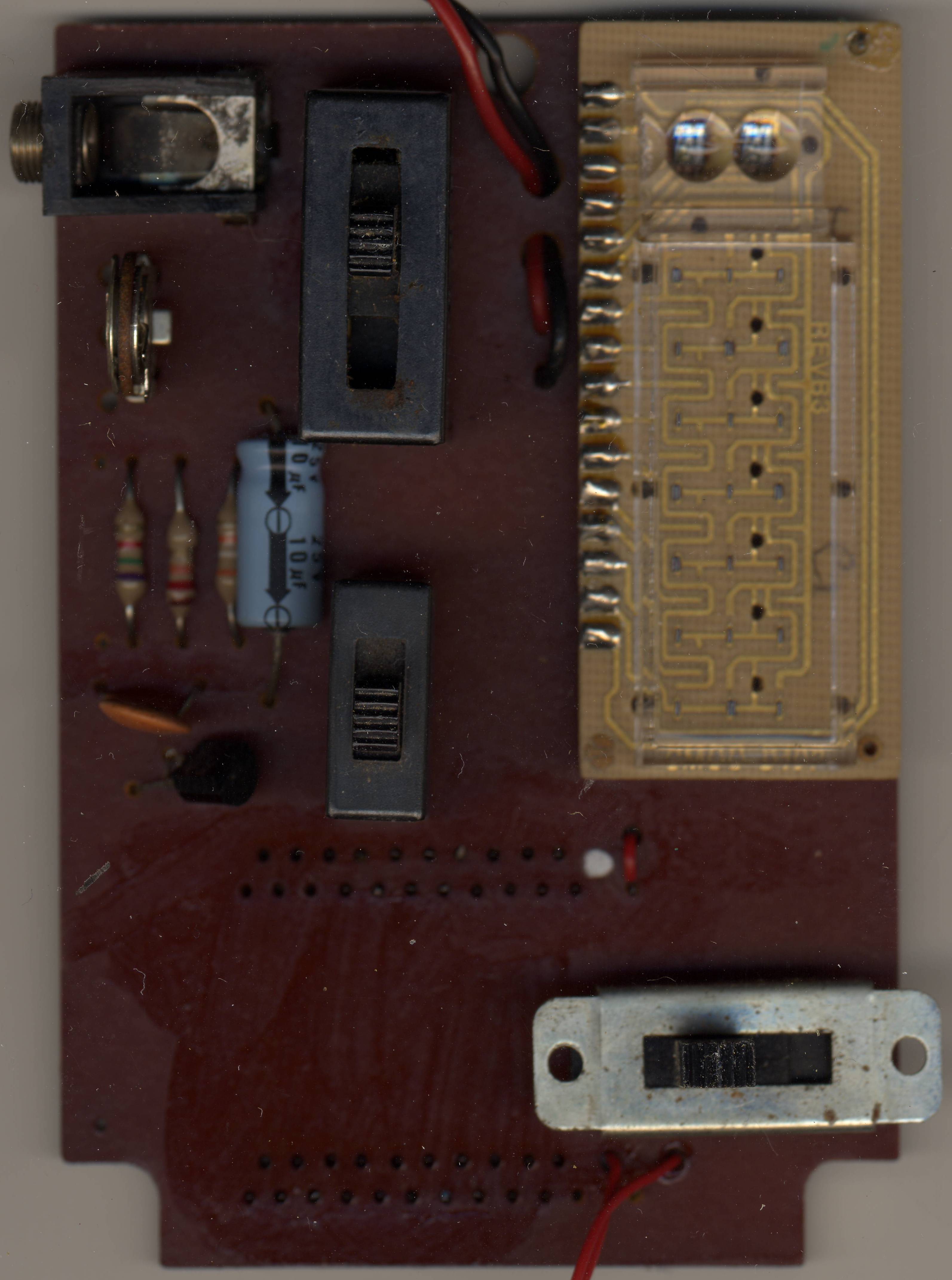
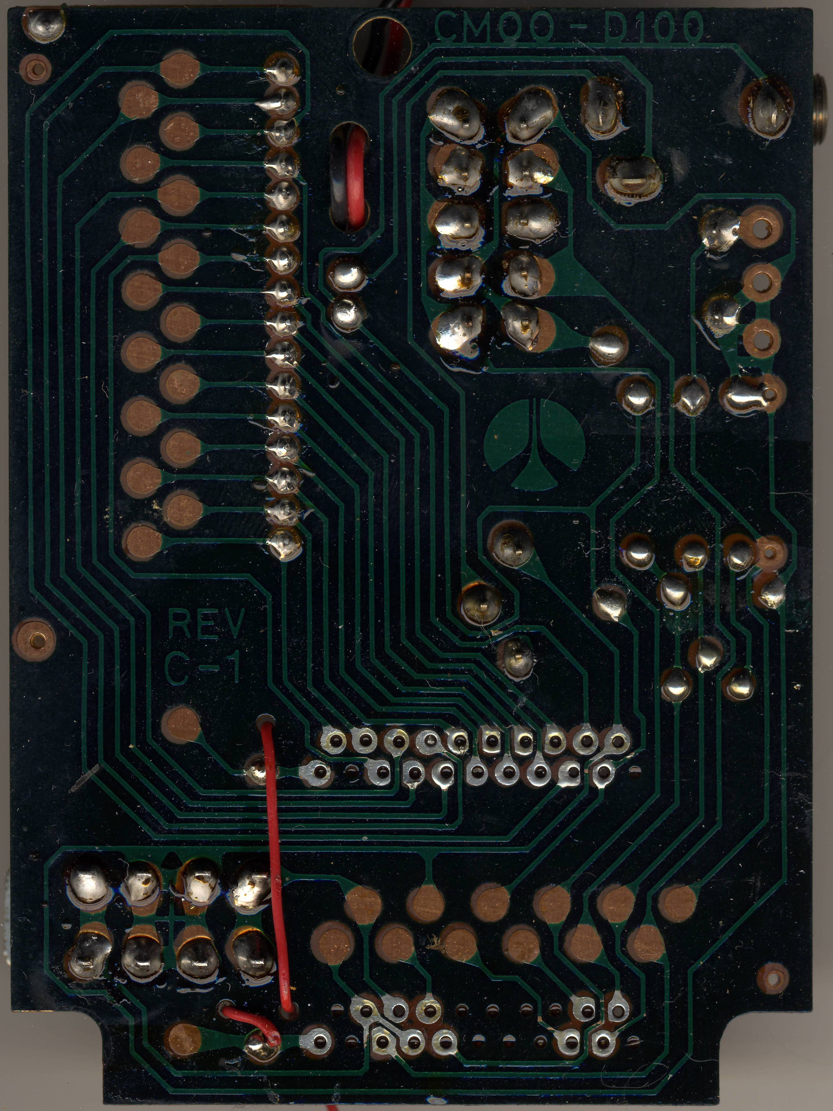
The electrolytic capacitor in the Mattel Auto Race (model 9879). Mattel and Rockwell published no schematic or parts list for the game. The values here are read from Sean Riddle's scans of one Auto Race main board, marked CM00-D100 REV C-1, which carries a single electrolytic capacitor.[1] Other board revisions may differ, so check your own board against the table before ordering parts.
Signs that the capacitor needs attention
[edit | edit source]- Brown or crusty residue on the board round the capacitor, or a split or swollen sleeve.
- Erratic play that a fresh battery does not cure. Mattel's leaflet puts a worn battery first for a misbehaving display, so rule it out before suspecting the capacitor.[2]
- See Capacitor Failure Symptoms.
Capacitor list
[edit | edit source]| Part | Type | Value as printed | Position | Notes |
|---|---|---|---|---|
| Electrolytic | Axial, blue sleeve | 25 V, 10 µF | Left side of the component side, below the speed trimmer and beside three resistors | The sleeve's arrows point to the negative end, towards the transistor[1] |
| Disc ceramic | Orange disc | Not legible in the scan | Below the electrolytic, next to the transistor | Ceramic; does not need replacing on age alone[1] |
No other electrolytic capacitor is visible on either side of that board or on its display board.[1] The board has no designators printed beside the capacitors, so the table describes them by position.
Recording your own board
[edit | edit source]- Take the battery out and open the case; see Mattel Auto Race General Maintenance.
- Photograph both sides of the main board before touching anything.
- Read the value, voltage and polarity printed on each electrolytic. Note which end the stripe or arrows point to.
- Note the board marking (CM00-D100 and the revision letter on the solder side) so that differences between revisions can be recorded.[1]
Replacement procedure
[edit | edit source]- Take the battery out.
- Open the case and lift the main board out, noting the wire routing.
- Mark the speed trimmer's position before working beside it; it sets the game's speed.[3]
- Note the polarity of the old capacitor, then desolder it.
- Fit a 10 µF capacitor rated 25 V or higher. The original is axial; a radial part fits if its leads are bent to reach the two holes and it sits flat enough for the case to close.
- Match the polarity to your notes.
- Clean off flux with isopropyl alcohol and reassemble.
Recommended parts
[edit | edit source]- One 10 µF electrolytic, 25 V or higher, axial or small radial, 85 °C or 105 °C.
- A new 9 V snap if the old one is corroded; see Mattel Auto Race General Maintenance.
Checks after replacement
[edit | edit source]| Check | Expected | Source |
|---|---|---|
| Switch to START in first gear | Track and timer light; the race starts | [2] |
| All four gears | Oncoming cars come faster in each higher gear | [2][4] |
| Steering | The car moves between all three lanes | [2] |
| Sound | Engine sound in play; victory or defeat sound at the end | [2][4] |
Related pages
[edit | edit source]- Mattel Auto Race
- Mattel Auto Race General Maintenance
- Mattel Auto Race Troubleshooting Guide
- Capacitor Failure Symptoms
- Recommended Tools
References
[edit | edit source]- ↑ 1.0 1.1 1.2 1.3 1.4 Sean Riddle, Auto Race circuit board scans, front and back (retrieved 2026-10-19), hosted here as File:Mattel Auto Race circuit board, component side.jpg, File:Mattel Auto Race circuit board, solder side.jpg and the detail File:Mattel Auto Race circuit board, capacitor and speed trimmer.jpg. Read from the scans: solder side marked CM00-D100 and REV C-1; on the component side a single blue axial electrolytic printed "25V 10µF" with arrows towards its negative end, an orange disc ceramic, three resistors, a transistor, a trimmer and a jack socket; no designators beside the capacitors; no other electrolytic on the main or display board.
- ↑ 2.0 2.1 2.2 2.3 2.4 Mattel, Inc., Mattel Electronics Auto Race Game Instructions, code 9879-0920(B), 1976; hosted here as File:Mattel Electronics Auto Race Instructions 9879-0920.pdf. PDF p. 2: start in first gear; shift to higher gears to vary the speed; steer between three lanes; the sound of victory or defeat. PDF p. 6: malfunctioning blips or timer are "the first sign of battery wear".
- ↑ Handheld Games Museum, "Mattel Auto Race" (retrieved 2026-10-19): the internal speed control, usually set about the middle.
- ↑ 4.0 4.1 Richard S. Chang and George J. Klose (Mattel, Inc.), US Patent 4,162,792, "Obstacle game", 1979: the gear switch sets the rate at which obstacles approach; engine sound rising in pitch with higher gears; victory beeping or a monotone defeat sound at the end of the race.