

ColecoVision
 | |
| ColecoVision with its two hand controllers (Evan-Amos, public domain) | |
| Specifications | |
|---|---|
| Manufacturer | Coleco Industries; distributed outside North America by CBS Electronics |
| Type | Home video game console |
| Released | August 1982 (North America); July 1983 (Europe)[1] |
| Discontinued | 1985[1] |
| Units sold | More than 2 million[1] |
| CPU | Zilog Z80A, 3.58 MHz[2] |
| Memory | 1 KB RAM (two 1K × 4 static RAMs); 16 KB video RAM (eight 16K × 1 dynamic RAMs); 8 KB BIOS ROM[2][3] |
| Storage | ROM cartridges of up to 32 KB[2] |
| Display | RF output on channel 3 or 4[4] |
| Sound | Texas Instruments SN76489AN: three tone generators and a noise generator[2][5] |
| Graphics | Texas Instruments TMS9928A video display processor; 256 × 192 pixels, 15 colours plus transparent, 32 sprite planes[2] |
| Input | Two hand controllers, each with a control stick, two side buttons and a numeric keypad[4][2] |
| Ports / interface | Cartridge slot (30-way), two 9-pin controller sockets, 60-way Expansion Module Interface, RF game cable socket, four-pin power socket[3] |
| Power | External supply, Coleco model 74942: +5 V 0.9 A, −5 V 0.1 A, +12 V 0.3 A[6] |
| OS / Firmware | OS 7, in the BIOS ROM[7] |
| Model no. | 2400 |
The ColecoVision (model 2400) is Coleco Industries' cartridge video game console, launched in North America in August 1982 and sold in Europe from July 1983 by CBS Electronics as the CBS ColecoVision.[1] It is built around a Zilog Z80A processor, a Texas Instruments TMS9928A video display processor with 16 KB of its own video RAM, and an SN76489 sound generator.[2] The power supply is a separate wall unit that delivers +5 V, +12 V and −5 V to the console through a four-wire lead.[2][6] A 60-way edge connector behind the door on the front, the Expansion Module Interface, carries the whole processor bus for add-ons such as the Atari 2600 adapter and the Adam computer.[2]
Care and cleaning are on ColecoVision General Maintenance, fault-finding on ColecoVision Troubleshooting Guide and the electrolytic capacitors on ColecoVision Capacitor Replacement Guide.
History
[edit | edit source]Coleco had sold dedicated Telstar consoles and tabletop electronic games before the ColecoVision. The console went on sale in August 1982 with a catalogue of twelve cartridges and Nintendo's Donkey Kong packed in, and Coleco sold more than 500,000 by Christmas that year. CBS Electronics distributed it outside North America as the CBS ColecoVision. Total sales passed 2 million before Coleco left the video game business in 1985.[1] Coleco's parts list for the console includes the Donkey Kong cartridge and its instruction book alongside the carton and packing inserts.[3]
Expansion Module #1, which plays Atari 2600 cartridges, led to a dispute with Atari that was settled with Coleco licensed under Atari's patents.[1] Expansion Module #3 turned the console into the Coleco Adam computer.
Hardware
[edit | edit source]Coleco's repair manual divides the console into five parts: the processor, the video section, the audio section, the RF modulator and memory.[2] Two boards sit inside the case: the logic board (Coleco part S75747) and a separate RF board (S75748), joined to the logic board by an 8-pin riser, J4.[3]
| Position | Part | Coleco part no. |
|---|---|---|
| U1 | Z80A processor | R73069 |
| U2 | 8K × 8 masked BIOS ROM | R73108 |
| U3, U4 | 1K × 4 static RAM (2114) | R73071 |
| U5, U6 | 3-to-8 decoder (74LS138) | R73072 |
| U7 | Hex inverter, open collector (74LS05) | R73073 |
| U8 | Dual D flip-flop (74LS74) | R73074 |
| U9 | Video display processor (TMS9928A), on a heat sink | R73075 |
| U10-U17 | 16K × 1 dynamic video RAM (4116) | R73076 |
| U18, U19 | Octal buffer (74LS541), one per controller port | R73077 |
| U20 | Sound generator (SN76489AN) | R73078 |
| U21 | RF modulator, on the RF board | Order RF board |
| U22 | Hex inverter (74LS04) | R73079 |
| U23 | CMOS quad bilateral switch (4066) | R73030 |
| U24 | Quad NAND gate (74LS00) | R73113 |
| U25, U26 | 22 kΩ resistor packs | R73114 |
| Y1 | 7.15909 MHz crystal | R73276 |
Positions, descriptions and part numbers are from Coleco's parts list;[3] the type numbers in brackets are from the KiCad redrawing of the schematic[8] and Evan-Amos's photograph of a board marked 75743 Rev H2-1.[9]
The clock comes from a 7.15909 MHz crystal divided by two in a D flip-flop, which gives the 3.58 MHz needed for the colour burst and for the processor. The video processor's 10.7 MHz clock is the third harmonic of the 3.58 MHz signal, picked out by a wave-shaping circuit.[2] The theory section prints the crystal as 7.19 MHz; the parts list gives 7.15909 MHz,[3] twice the 3.579545 MHz that the manual's oscilloscope pages specify at U1 pin 6.[10]
Memory is split three ways. The 8 KB system ROM holds frequently used subroutines; cartridges map up to 32 KB of ROM in four 8 KB banks selected by the U5 decoder; and two 1K × 4 static RAMs give 1 KB of working RAM.[2] The video processor has its own 16 KB of dynamic RAM in eight 16K × 1 chips, U10 to U17, which it refreshes itself.[2]
Power supply
[edit | edit source]The whole power supply is in the plug-in wall unit: a step-down transformer, rectifiers, filters and regulators that output +5 V, +12 V and −5 V. Coleco's manual describes the unit as ultrasonically welded and not serviceable, and says a faulty one should be replaced as a whole.[2]
| Pin | Output | Rated current | Wire colour inside the console |
|---|---|---|---|
| 1 | +5 V DC | 0.9 A | White |
| 2 | −5 V DC | 0.1 A | Blue |
| 3 | +12 V DC | 0.3 A | Red |
| 4 | Ground | – | Black |
Pin numbers, outputs and currents from a photograph of the supply's label;[6] wire colours from the schematic redrawing.[8] The CBS supply for European consoles takes 220-250 V at 50 Hz, and on the CBS PAL console two of the four wire colours differ.[6]
The power switch, S2, is a double-pole slide switch on the logic board. It switches +5 V and +12 V; the −5 V line runs through inductor L4 without passing through the switch, so −5 V is on the board whenever the supply is plugged in.[8][11] Callan Brown notes that only the video RAM uses the −5 V rail.[11]
Video and sound
[edit | edit source]The TMS9928A runs in Graphics I mode for ColecoVision games: a 256 × 192 pixel screen in 15 colours plus transparent, built from a backdrop, a pattern plane and 32 sprite planes. It sends a non-maskable interrupt to the processor about every 1/60 second and outputs three signals, luminance and two colour-difference signals (Y, R-Y and B-Y), to the RF modulator.[2][8] A 4066 analogue switch on the logic board, U23, selects either the console's video or video from an expansion module.[2][8]
The SN76489 sits on the processor data bus and has three tone generators and a noise generator; its audio goes to the RF modulator.[2][5] The RF modulator puts out channel 3 or channel 4, chosen with the switch on the back of the console.[4]
Controllers and expansion
[edit | edit source]Each hand controller has an eight-direction control stick, two side buttons and a numeric keypad that takes a printed overlay for some games. The controllers plug into sockets inside their storage bays on top of the console.[4] The console reads them through two ground strobes and five inputs per port, buffered by U18 and U19. Each port also has a two-line spinner interface that reads a pair of square waves for direction and speed and interrupts the processor.[2]
Coleco's add-ons:
- ColecoVision Expansion Module 1, which plays Atari 2600 cartridges through the Expansion Module Interface.
- ColecoVision Expansion Module 2, a steering wheel and accelerator pedal that, despite the name, plugs into a controller port.[1]
- ColecoVision Expansion Module 3, the Coleco Adam computer in a form that attaches to the console.
- ColecoVision Roller Controller, a trackball.
- ColecoVision Super Action Controller, a pair of hand-grip controllers with a speed roller.
Versions
[edit | edit source]The US console is model 2400; the ColecoVision & ADAM Computer Museum site records box numbers 2400-CA for Canada, 6989-8 for the CBS console in the UK and the rest of Europe, 6989-8F for France, LNC240001 for Argentina and ABC 240040 for Australia.[12] On NTSC consoles the BIOS holds the title screen for about 12.7 seconds; CBS cut this to about 3.3 seconds on PAL and SECAM consoles.[1] A French CBS version of 1983 has audio and video output on a SCART connection.[6][12]
Wikipedia gives the TMS9929A video processor for PAL consoles.[1] The community redrawing of the PAL logic board shows a TMS9928A followed by an LM1889 modulator and a 4.433618 MHz crystal.[13] Read the chip on your own board before ordering a replacement.
Repair
[edit | edit source]Coleco wrote a full service manual for repair centres, the ColecoVision Technical Manual, with a parts list, a component location drawing of the logic board, fifteen troubleshooting flow charts, oscilloscope pictures of the signals and a page of technical tips. The surviving scan lacks page V-1, the schematic.[2][5]
ColecoVision.dk ranks the power supply as the most common failure, then the video RAM and the on/off switch, followed by the controller buffers U18 and U19 and, less often, the video processor.[6] Callan Brown calls a dirty power switch the most common ColecoVision repair; the usual symptom is a scrambled or black picture.[11] Coleco's manual shows the corrupted title screen that each of the eight video RAM chips produces when it fails; see ColecoVision Troubleshooting Guide.[14]
The two boards have seven aluminium electrolytic capacitors and one tantalum between them, all small: C3 (1 µF) and C16, C34, C36, C68, C73, C87 and C106 (10 µF; C106 is the tantalum and C73 is on the RF board).[3] Their positions are on ColecoVision Capacitor Replacement Guide.
Documentation
[edit | edit source]- ColecoVision Documentation: Coleco's ColecoVision Technical Manual, the Owners Manual (Guide No. 78200A) and the KiCad redrawing of the logic board schematic.
Gallery
[edit | edit source]-
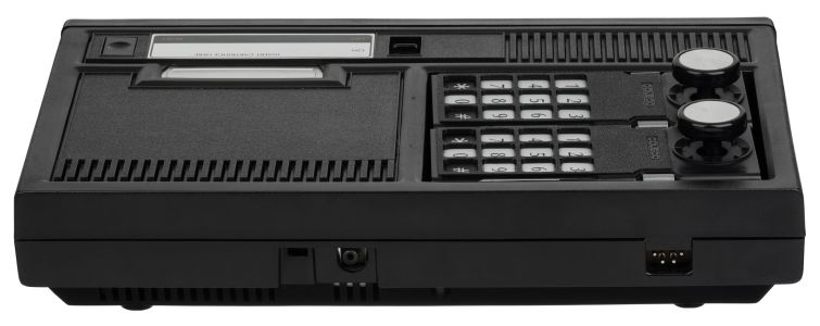 Rear: channel selector, game cable socket and, at right, the four-pin power socket (Evan-Amos, public domain)
-
 With the top casing and the top RF shield off (Evan-Amos, public domain)
-
 Logic board 75743 Rev H2-1 (Evan-Amos, public domain)
-
 Coleco's component location drawing of the logic board (Technical Manual p. V-3)


Related pages
[edit | edit source]- ColecoVision General Maintenance
- ColecoVision Troubleshooting Guide
- ColecoVision Capacitor Replacement Guide
- ColecoVision Documentation
- ColecoVision Expansion Module 1
- ColecoVision Expansion Module 2
- ColecoVision Expansion Module 3
- ColecoVision Roller Controller
- ColecoVision Super Action Controller
- Coleco Adam
- Coleco Gemini
References
[edit | edit source]- ↑ 1.0 1.1 1.2 1.3 1.4 1.5 1.6 1.7 1.8 Wikipedia, "ColecoVision" (retrieved 2026-10-19), used for history only: North American launch in August 1982 with twelve games and Donkey Kong as the pack-in; European release by CBS Electronics in July 1983; more than 500,000 sold by Christmas 1982 and over 2 million in total; discontinuation in 1985; Expansion Module #1 and the Atari dispute settled with Coleco licensed under Atari's patents; Expansion Module #2 plugging into a controller port; the 12.7-second title delay on NTSC consoles cut to 3.3 seconds on PAL and SECAM consoles; the Roller Controller power connector incompatibility with Expansion Module #3.
- ↑ 2.00 2.01 2.02 2.03 2.04 2.05 2.06 2.07 2.08 2.09 2.10 2.11 2.12 2.13 2.14 2.15 2.16 2.17 2.18 Coleco Industries, ColecoVision Technical Manual (called the ColecoVision Repair Manual in its introduction), section III, pp. III-1 to III-6 (system description, block diagram, CPU, video display processor, memory, RF modulator, hand control interface, power supply). Hosted here as File:ColecoVision Repair Manual.pdf (see ColecoVision Documentation).
- ↑ 3.0 3.1 3.2 3.3 3.4 3.5 3.6 Coleco Industries, ColecoVision Technical Manual, section V, parts list pp. V-10 to V-18: capacitors, connectors J1-J6, crystal Y1 (7.15909 MHz), diodes, inductors L1-L17, integrated circuits U1-U26, resistors, switches S1-S3, transistors, and miscellaneous parts including the power supply (S55416), logic board (S75747), RF board (S75748), hand controller (S78022), Donkey Kong cartridge (S78021), heat sink for U9 (F74937), RF box parts and housings. Parts on the RF board are listed as "Order RF board".
- ↑ 4.0 4.1 4.2 4.3 Coleco Industries, ColecoVision Owners Manual, model 2400, Guide No. 78200A, 1982: connecting the antenna switch box and game cable; plugging in the power supply with the console switched off; the channel 3/4 selector on the rear; inserting and removing cartridges with the power switch off; the hand controllers (keypad, eight-direction control stick, side buttons, overlay slot); care of the game; the owner's troubleshooting chart. Hosted here as File:ColecoVision Owners Manual Guide 78200A.pdf.
- ↑ 5.0 5.1 5.2 Coleco Industries, ColecoVision Technical Manual, section VI, pp. VI-1 to VI-27: test equipment (35 MHz oscilloscope, 80 MHz frequency counter, RF preamplifier, colour TV, diagnostic cartridge, spinner interface tester); the diagnostic cartridge's ROM, RAM, video, sound and controller tests; the assumptions behind the flow charts; flow chart sheets 1-15 (overview, no picture, scrambled picture, bad colour, miscellaneous picture faults, audio, power supply, logic section, video section, RF, 3.58 MHz clock, 10.7 MHz clock, U6, hand controller, spinner interface).
- ↑ 6.0 6.1 6.2 6.3 6.4 6.5 ColecoVision.dk, "ColecoVision Technical" (retrieved 2026-10-19): photograph of the label of Coleco power supply model 74942 (input 120 V AC 60 Hz 0.25 A; pin 1 +5 V DC 0.9 A, pin 2 −5 V DC 0.1 A, pin 3 +12 V DC 0.3 A, pin 4 ground; made in Taiwan); a CBS Electronics supply for 220-250 V 50 Hz; the wire colours of the CBS PAL version changing from blue to yellow and from black to blue between the supply and the console; the site's view that the power supply fails most often, then the video RAM, then the on/off switch, with U18, U19 and the video processor also failing; Coleco's technical tips retyped by Ole Nielsen; photographs of the Expansion Module #2 board (PCB 55888 Rev D) and the Roller Controller board.
- ↑ Coleco Industries, ColecoVision Programmers Guide, revision 5, 30 November 1982, Internet Archive item colecovision-programmers-guide-revision-5 (retrieved 2026-10-19): Coleco's in-house guide for programming the ColecoVision through the operating system calls of OS 7, built into the console.
- ↑ 8.0 8.1 8.2 8.3 8.4 Colecovision Logic Blocks, nine-sheet KiCad redrawing of the ColecoVision logic board schematic, revision J (2021), author not recorded. Sheet 3: power filters and switch (wire colours white +5 V, red +12 V, blue −5 V, black ground; S2 switching +5 V and +12 V through L6 and L5; −5 V through L4); sheet 4: SN76489AN and C16; sheet 5: clock and reset, C3; sheet 7: A/V switcher, U23, C68, C87; sheet 8: TMS9928A and the eight 4116s, with L2 and C34 on −5 V and L3 and C36 on +12 V, and C106 at VDP pin 33; sheet 9: Z80, BIOS, 2114 RAMs and decoders. Hosted here as File:ColecoVision console schematic (KiCad redraw, rev J).pdf.
- ↑ Evan-Amos, photograph of a ColecoVision logic board, from Wikimedia Commons (public domain): silkscreen "75743 REV H2-1" and "© 1982"; ITT 4116 video RAMs, Toshiba TMM314APL-1 static RAMs, TMS9928A under a finned heat sink, SN76489AN, 74LS541N buffers, the RF shield box, the slide switch S2 and the four-wire power harness; C36 marked 10 µF 16 V.
- ↑ Coleco Industries, ColecoVision Technical Manual, section VII, Pictures of Signals, pp. VII-1 to VII-22: oscilloscope settings and expected waveforms at C66 and C67 (R-Y and B-Y video), J4 pins 2, 3, 4, 6, 7 and 8 (audio, R-Y, +12 V ripple, composite video, B-Y, RF clock at 3.579545 MHz ± 100 Hz), the base of Q6 (Y video), U1 pins 6, 16, 17, 18, 19, 20, 22, 24, 27, 28 and 35, U6 pin 5 and U7.
- ↑ 11.0 11.1 11.2 Callan Brown, "Colecovision Power Switch Fix/Upgrade" (retrieved 2026-10-19): a dirty power switch giving a scrambled or black picture, called the most common ColecoVision repair; the three rails, with −5 V always on and used only by the video RAM; dismantling the console (bottom screws, RF shield screws and one soldered corner, board screws); cleaning the switch contacts after desoldering the two clips that hold its top half; replacing it with a panel-mounted double-pole switch, keeping the +5 V column (towards the board edge) and the +12 V column (towards the middle) separate.
- ↑ 12.0 12.1 ColecoVision & ADAM Computer Museum (DiRoccoVision), "ColecoVision Console" (retrieved 2026-10-19): box and model numbers 2400 (USA), 2400-CA (Canada), 6989-8 (UK and Germany), 6989-8F (France), LNC240001 (Argentina, Kenia), ABC 240040 (Australia); a French SCART version; two black controllers with every console.
- ↑ Colecovision Logic Blocks, KiCad redrawing of the PAL ColecoVision logic board, revision D, author not recorded, from the colecovisionadam.com Documents page ("CV Console PAL-Schematic", retrieved 2026-10-19): TMS9928A, LM1889 and a 4.433618 MHz crystal.
- ↑ Coleco Industries, ColecoVision Technical Manual, section VIII, Technical Tips, pp. VIII-1 to VIII-3: black-out after a short time (C106 polarity); purple Donkey Kong characters (U9); keypad not selecting games (U6); channel 3 but not channel 4 (RF board); not all cartridges working (C70, U5); vertical lines on the background (C106); menu skipped (U18, U19 pin voltages below 2.2 V); no explosion sound (U20); +12 V shorted to −5 V (WJ2); no voltage to the RF board (WJ2); no colour (3.57954 MHz ± 100 Hz at J4 pin 8); double image (U9); wavy picture (R62 270 Ω, C90 120 pF, an ITT transistor at Q2); incorrect scoring (U3, U4); wrong clock frequency with a Texas Instruments U22; spinner interface faults with a Texas Instruments U24; slow game (U20); and photographs of the scrambled title screens produced by failed U10 to U17.
