

Apple II Plus
 | |
| Apple II Plus | |
| Specifications | |
|---|---|
| Manufacturer | Apple Computer, Inc. |
| Type | Personal computer |
| Released | June 1979 |
| Discontinued | December 1982 |
| Intro price | US$1,195 at introduction |
| CPU | MOS Technology 6502 @ 1.023 MHz |
| Memory | 48 KB RAM standard (16 KB and 32 KB also sold); 64 KB with a 16 KB Language Card. 12 KB ROM |
| Storage | Cassette interface; optional Disk II 5.25-inch floppy drive |
| Display | 40×24 text; 40×48 low-resolution, 16 colours; 280×192 high-resolution, 6 colours |
| Sound | 1-bit speaker toggled at $C030 |
| OS / Firmware | Apple DOS 3.2, DOS 3.3; ProDOS from 1983 |
| Predecessor | Apple II |
| Successor | Apple IIe |
| Model no. | Sold as 16 KB, 32 KB and 48 KB systems; Bell & Howell A2S1048B and A2S1032B |
The Apple II Plus is the second model in Apple Computer's Apple II series, introduced in June 1979 and made until December 1982.[1] It is an Apple II with Applesoft BASIC in ROM in place of Integer BASIC, the Autostart Monitor in place of the original Monitor, and 48 KB of RAM as the standard fit.
Architecture and processor
[edit | edit source]The Apple II Plus uses a MOS Technology 6502 at 1.023 MHz. All system timing is derived from a single 14.318 MHz master oscillator, which also produces 7.159 MHz, the 3.58 MHz colour reference and the two 1.023 MHz phases of the system clock. Neither the 14 MHz signal nor the colour reference is brought out to the peripheral connectors.[2]
The 6502 has an 8-bit data bus and a 16-bit address bus, for a 64 KB address space. The board brings the bus out to eight peripheral slots, numbered 0 to 7, each with address, data, interrupt and DMA lines. The INH (ROM inhibit) line runs to every slot, and a card that pulls it low disables every ROM on the main board.[2]
Firmware
[edit | edit source]The II Plus ROM is 12 KB in six 2 KB devices, in sockets silkscreened with the address range each covers (ROM-D0 to ROM-F8). Applesoft II BASIC occupies D0, D8, E0, E8 and F0 (10 KB) and the Autostart Monitor F8 (2 KB).[2]
There is no Integer BASIC in a II Plus. Applesoft replaced it, and with it went the Mini-Assembler, the Floating-Point Package and Wozniak's SWEET-16 interpreter, all of which lived in the Integer ROMs.[2] The Monitor's STEP and TRACE commands went the same way.[1] Owners of an original Apple II could get Applesoft without buying a new machine by fitting the Applesoft Firmware Card in slot 0; the two BASICs share the same memory and cannot be used at once, and switching between them erases the program in memory.[1]
The Autostart Monitor is what makes a II Plus boot a disk on its own. At power-on it clears the screen, then scans the slots from 7 down to 1, examining the first few bytes of each card's ROM for the signature of a Disk II controller, and passes control to the first one it finds. If no controller is present it enters BASIC.[1]
The Autostart ROM also introduced the soft-entry vector at $3F2-$3F3, the address RESET returns to, and the power-up byte at $3F4, which must equal the high byte of that address exclusive-ORed with $A5. If it does not match, the Monitor assumes power has just been applied and does a cold start.[2] A warm RESET through the soft-entry vector leaves a BASIC program and its variables intact.[1]
Memory
[edit | edit source]RAM sits in three rows of eight devices, rows C, D and E, with row C nearest the front of the board. Each row must hold eight of the same type.[2] A II Plus is normally fitted with 4116-type 16K×1 devices throughout, giving 48 KB.
Because 16K parts had become cheap enough that Apple no longer expected anyone to fit 4K devices, Apple II History says the strapping blocks that let an original Apple II mix 4K and 16K rows were removed from the II Plus.[1] Some II Plus boards still carry them, as in the board photograph below, in the "memory select" sockets at D1, E1 and F1; all three must be strapped identically.[2] Clean them and refit them the same way round.
4116 RAM needs +12 V and −5 V as well as +5 V,[3] so a sagging −5 V or +12 V rail shows up as a memory failure. Check the rails before pulling RAM.
A 16 KB Language Card in slot 0 takes a 48 KB machine to 64 KB.[2]
Display and graphics
[edit | edit source]The display modes are 40 × 24 text, upper case only as shipped; 40 × 48 low-resolution graphics in 16 colours; and 280 × 192 high-resolution graphics in 6 colours, with limits on the colour of individual dots.[2] Video leaves on an RCA phono jack.[1]
Lower case was not supported. It was the commonest user modification of the period, usually a small board under the keyboard. From the Revision 7 board of 1981 Apple changed the method of character generation - partly to reduce radio-frequency interference - and on a Revision 7 board lower-case characters can be displayed by adding a single chip. Without a third-party keyboard encoder, only upper case can be typed.[1]
Sound
[edit | edit source]A small 8 Ω speaker, toggled by any access to $C030 (49200). Every tone is produced by software timing those accesses.[2]
Input/output and expansion
[edit | edit source]Standard connections are the composite video output, cassette input and output, the 16-pin game I/O connector, the built-in keyboard, and the eight peripheral slots.
The keyboard was revised repeatedly. The original RESET key had the same feel as the keys around it, which made it easy to hit by accident; Apple first fitted a stiffer spring and then made RESET require CTRL to be held as well, with a small slide switch inside the case to select the behaviour.[1]
The shift-key modification was the other common change: a wire from the contact under the SHIFT key to push-button 2 of the game port ($C063), so that software can tell whether SHIFT is pressed. PB2 belongs to an optional second pair of paddles.[1] See Apple IIe for the conflict when a hand control does use that input.
Bell & Howell models
[edit | edit source]Apple licensed Bell & Howell to sell black-cased Apple II and II Plus machines into American schools. These have screws on the back to retain the lid, because UL certification, often required for school equipment, needed the case closed; an ordinary II Plus is designed to run with the lid off. Model A2S1048B carries a rear "backpack" adding coaxial video out, three mains outlets, a carrying handle, three audio inputs, an audio output and a headphone jack; model A2S1032B has no backpack. Both were shipped with the shift-key modification already made, and both have DIN sockets on the right-hand side for external game paddles.[1]
Power supply
[edit | edit source]The supply is Apple's own switch-mode design, built by Astec, and it is the machine's characteristic failure. Apple's published figures are +5.0 V, +11.8 V, −12.0 V and −5.2 V, so "+12 V" and "−5 V" are not the nominals, and the Reference Manual gives no per-rail tolerance.[2] The primary reservoir capacitors are 47 µF 250 V, and there is a 0.1 µF class-X capacitor across the mains.[4]
A ticking supply is the protection working. If an output is short-circuited a feedback circuit stops the oscillator, all outputs drop, and the supply retries after about a second.[2] Pull every card and disconnect the drives before concluding the supply is faulty.
Full procedures, the component listings and the load-test resistor values are on Apple II General Maintenance. Apple's later replacement supply (661-0455) is 1.5 inches longer and fits any Apple II or II Plus.[5]
Troubleshooting
[edit | edit source]Apple's service manual for the Apple II and II Plus has a troubleshooting chart and a chip swapping chart by board location; both are reproduced on Apple II General Maintenance.[5] Apple's parts list gives the RFI Apple II Plus main board with RAM as 661-91207 and the Autostart F8 ROM as 342-0020.[5]
PCB and schematics
[edit | edit source]The main logic board is a single board carrying the CPU, RAM, ROM, video and bus logic. Revision 7 of 1981 changed the character generation.[1]
| Logic Board | Schematic Diagrams |
|---|---|
 |
 |
Things that are not faults
[edit | edit source]- A supply that ticks about once a second with a card or drive connected is protecting itself against a load fault.[2]
- A "+12 V" rail reading 11.85 V is on Apple's nominal of +11.8 V.[2]
- Coloured dots in high-resolution graphics cannot all be set independently; Apple documents limits on the colour of individual dots.[2]
Gallery
[edit | edit source]-
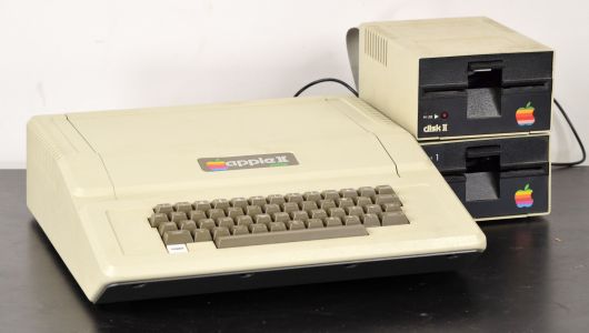 Apple II Plus front view
-
 Apple II Europlus with Disk II drives
-
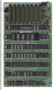 Apple II j-plus main logic board

See also
[edit | edit source]- Apple II General Maintenance
- Apple II Reference Manual
- Disk II
- Capacitor Failure Symptoms
- Apple II and II Plus Technical Procedures
References
[edit | edit source]- ↑ 1.00 1.01 1.02 1.03 1.04 1.05 1.06 1.07 1.08 1.09 1.10 1.11 Steven Weyhrich, Apple II History, Chapter 6, "The Apple II Plus", apple2history.org. Introduction June 1979 and end of production December 1982; introduction price of $1,195; 48K standard with 16K and 32K versions also available; removal of the RAM strapping blocks; the Autostart ROM's slot scan and the features dropped from the ROMs; the Revision 7 board of 1981 and its character generation change; the RESET key changes and the shift-key modification; the Bell & Howell models.
- ↑ 2.00 2.01 2.02 2.03 2.04 2.05 2.06 2.07 2.08 2.09 2.10 2.11 2.12 2.13 2.14 Apple II Reference Manual, Apple Computer, Inc., 1979 - hosted on this wiki as File:Apple II Reference Manual 1979.pdf. Power supply specification page 92 (input range, supply voltages +5.0/+11.8/−12.0/−5.2 V, full-load currents, 60 W and 79 W, short-circuit shutdown and restart); main board description (three RAM rows C, D and E, six ROM sockets silkscreened by address range, memory configuration blocks at D1/E1/F1, eight peripheral slots 0 to 7); ROM section (74LS138 at F12, INH line, 9316B pinout and the chip-select polarity difference from 2316/2716); RAM section (4096-family and 4116-type devices, nine configurations, Language Card to 64K); keyboard section (MM5740 decoder, 7400 oscillator at U4, 555 at U3); system timing Table 27; Apple II Plus section (Mini-Assembler, Floating-Point Package and SWEET-16 not available on the II Plus).
- ↑ Mostek, MK4116P-2/3 16,384 × 1 Bit Dynamic RAM data sheet, copy at https://console5.com/techwiki/images/8/85/MK4116.pdf . VDD +12 V, VCC +5 V and VBB −5 V, each ±10%.
- ↑ Apple Products Information Package - Astec Power Supplies, Apple Computer, Inc., 6 August 1982 - hosted on this wiki as File:Apple Astec Power Supplies Service Package 1982.pdf. Component listings for the Astec AA11040 and AA11040B, giving capacitor values and voltages, the 2.75 A fuse, the 260 VAC varistor and the inrush thermistor.
- ↑ 5.0 5.1 5.2 Apple Computer, Apple II/II Plus Technical Procedures, from Apple Service Technical Procedures: Apple II/Apple III Archived Products, Volume One (072-0231), hosted as File:Apple II and II Plus Technical Procedures.pdf. Section 3, Troubleshooting: Apple II Troubleshooting Chart and Chip Swapping Chart, pp. 3.3-3.8 (rev. Sep 82); Illustrated Parts List, pp. IPL.3-IPL.5 (rev. Jan 89): 661-91207 Apple II Plus motherboard RFI with RAM, 661-0455 power supply and the longer replacement supply, Applesoft ROMs 341-0011 to 341-0015 and Autostart F8 ROM 342-0020.