

Sharp MZ-1500
 | |
| An MZ-1500 in the KCG Computer Museum, with the built-in Quick Disk drive at top right (photo: うぃき野郎, CC BY-SA 4.0) | |
| Specifications | |
|---|---|
| Manufacturer | Sharp |
| Type | Home computer |
| Released | 1984 (Japan)[1] |
| Intro price | 89,800 yen[1] |
| CPU | Z80A at 3.579545 MHz[1] |
| Memory | 64 KB RAM; 4 KB text and attribute VRAM; 24 KB PCG VRAM[1] |
| Storage | Built-in Quick Disk drive, 64 KB per side[1][2] |
| Display | 40 × 25 text; 1,024 programmable 8 × 8 characters (PCG) for 320 × 200 graphics; 8 colours with palette[1] |
| Sound | Two Texas Instruments SN76489, plus an 8253 square-wave output[1] |
| ROM | 4 KB monitor 1Z-009B, 8 KB monitor 9Z-502M, 4 KB character generator[1] |
| Power | 100 V AC ±10%, 50/60 Hz, 28 W[1] |
| Dimensions | 440 × 305 × 109 mm[1] |
| Weight | 5 kg[1] |
| OS / Firmware | — |
| Predecessor | Sharp MZ-700 |
| Model no. | MZ-1500 |
The Sharp MZ-1500 is an 8-bit home computer that Sharp released in Japan in 1984. It keeps the design of the MZ-700 and adds a programmable character generator for graphics, two SN76489 sound chips, a colour palette and a built-in Quick Disk drive in place of the data recorder.[1][3] It was sold only in Japan.[3] The Japanese Wikipedia article gives the release date as 1 June 1984; the same encyclopaedia's article on the MZ series gives May 1984.[1][4]
Like other MZ machines, the MZ-1500 holds no BASIC in ROM. At power-on it tries to boot from the Quick Disk and, if that fails, shows a menu offering Quick Disk, floppy disk, cassette or the ROM monitor. The supplied BASIC, 5Z-001, came on Quick Disk.[1]
Hardware
[edit | edit source]The CPU is a Z80A clocked at 3.579545 MHz, below its rated 4 MHz, because the CPU clock is shared with the oscillator for the RF modulator.[1] The MZ-700's 4 KB monitor is kept as 1Z-009B, with some bugs fixed, and a second 8 KB monitor, 9Z-502M, handles booting from Quick Disk, floppy disk or a RAM board.[1]
The circuit diagram printed in Radio Gijutsu-sha's Sharp MZ-1500 Technical Note shows how the board is built. The CPU is a Sharp LH0080A at position 11H. A Z80 PIO (LH0081) handles the printer, a Z80 SIO (LH0084) the Quick Disk, an 8255 the keyboard and cassette, and an 8253 the timers and the MZ-700 sound. Main RAM is eight 4164 chips, the PCG uses three µPD4168C-20 RAMs and the text screen two 2016s. The board also carries an M60719 gate array clocked from a 14.3 MHz oscillator. The two SN76489s are at 4F and 3F, and an LM386 at 1I drives the speaker.[5]
There is no separate graphics VRAM. Graphics are drawn with the programmable character generator (PCG): 1,024 characters of 8 × 8 pixels, each pixel in any of eight colours, laid over the 40 × 25 text screen. The PCG layer can be shown in front of the text, between the text colour and the background, or not at all, and its patterns can only be rewritten during horizontal blanking.[1]
Each of the two SN76489 chips has its own output on the back of the machine; the internal speaker gets both mixed to mono. The MZ-700's 8253 square-wave sound is still present.[1]
Quick Disk drive
[edit | edit source]The Quick Disk (QD) mechanism was developed by Mitsumi and the disks by Hitachi Maxell, and Sharp was the first company to use it in a product. Ohishi identifies the drive as Mitsumi's first, top-loading model, the D280.[6] The MZ-1500 talks to the drive through a Z80 SIO.[1] A disk side holds up to 64 KB on one spiral track and is read sequentially, so a single file cannot be deleted or enlarged in place.[1][2] Sharp sold the same drive as the external MZ-1F11 for the MZ-700, MZ-800, MZ-2000 and MZ-2200.[6]
Connections and expansion
[edit | edit source]| Interface | Connector |
|---|---|
| Joysticks | Two, Sharp 5-pin |
| Digital RGB | 8-pin DIN |
| Composite video | One output |
| RF | Channel 1 or 2, colour or monochrome switchable |
| Data recorder MZ-1T03 | 8-pin mini-DIN |
| Audio cassette recorder | Read and write sockets |
| Printer | Card-edge connector; Centronics or Sharp MZ standard, set by system switch 2 on the back |
| Expansion | One general expansion slot, one RAM file slot, one voice board slot |
Ohishi notes that the single expansion slot, which sticks out about 3 cm from the back, has two connectors inside: the second takes the MZ-1R18 RAM file board. They are 50-way card-edge connectors.[7] The MZ-1U08 expansion box passes only I/O addresses 00h to C7h, so boards outside that range, such as the MZ-1E05 floppy interface, must go in the slot on the machine itself.[1][7]
Four system switches on the back set the polarity for an ordinary cassette recorder (switch 1), the printer interface (switch 2) and whether graphics are displayed at all (switch 3); switch 4 is unused.[8][8]
Power supply
[edit | edit source]The power supply is internal and runs from 100 V mains; the rating plate on the base gives 28 W.[1][7] Ohishi describes it as a single 5 V supply in its own metal case.[7] The clock has no battery backup.[1]
Known problems
[edit | edit source]- Corrupted characters after fitting extra boards, traced to a weak power supply and cured by recapping it or by fitting a new 5 V supply.[7]
- Quick Disks that turn stiffly or fail to load, from a stretched or broken drive belt, friction at the worn head cam, a dirty head or the older type of disk.[7][6]
- Keys that stop working, singly from dirty contacts or in whole rows from the keyboard's film cable connector.[7]
The details are in the repair guides below.
Documentation
[edit | edit source]Sharp did not print the MZ-1500's circuit diagram in its owner's manual. The circuit diagram and the monitor listing were published in Kogakusha's MZ-1500 Technical Manual, and Radio Gijutsu-sha's Sharp MZ-1500 Technical Note (1984) also carries a complete circuit diagram, in its appendix on pages 216 to 223.[4][1][5] A scan of the Technical Note is on the Internet Archive; it is a copyrighted book and is not hosted here. The circuit diagram gives no voltage ratings for most capacitors and does not cover the power supply. No Sharp service manual for the MZ-1500 has been found online. The documents for the MZ-1F11, the external version of the same Quick Disk drive, are described at Sharp MZ-1F11 Documentation:
- File:Sharp MZ-1F11 Instruction Manual.pdf: specifications, head cleaning and connector pin-outs.[2]
- File:Sharp MZ-1F11 Service Manual Supplement.pdf: troubleshooting flow charts and the head pad replacement procedure.[9]
Repair guides
[edit | edit source]- Sharp MZ-1500 General Maintenance
- Sharp MZ-1500 Troubleshooting Guide
- Sharp MZ-1500 Capacitor Replacement Guide
Gallery
[edit | edit source]-
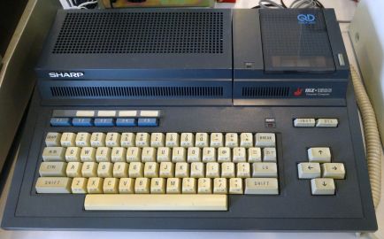 MZ-1500 (うぃき野郎, CC BY-SA 4.0)
-
 The built-in Quick Disk drive, with the BUSY lamp and eject button (うぃき野郎, CC BY-SA 4.0)

References
[edit | edit source]- ↑ 1.00 1.01 1.02 1.03 1.04 1.05 1.06 1.07 1.08 1.09 1.10 1.11 1.12 1.13 1.14 1.15 1.16 1.17 1.18 1.19 1.20 1.21 1.22 1.23 1.24 MZ-1500, Wikipedia (Japanese)—link(accessed 2026-10-21) Released by Sharp on 1 June 1984; Japan only; successor to the MZ-700 with its basic design kept; built-in Quick Disk drive, booted from Quick Disk first with a boot menu as fallback; Z-80A at 3.579545 MHz, the clock shared with the RF modulator's oscillator; 64 KB main RAM, 4 KB text and attribute VRAM, 24 KB PCG VRAM; monitors 1Z-009B (4 KB, MZ-700 compatible) and 9Z-502M (8 KB), 4 KB character ROM; two SN76489 sound chips, each with its own rear output and mixed to the internal speaker, plus the 8253 square-wave output of the MZ-700; 40 × 25 text, 1,024 definable 8 × 8 PCG characters in 8 colours, palette; 24-hour clock with no battery backup; 100 V AC ±10%, 50/60 Hz, 28 W; 440 × 305 × 109 mm, 5 kg; 89,800 yen; interfaces listed under "搭載インターフェイス"; expansion slot, RAM file slot and voice board slot; MZ-1U08 expansion box limited to I/O addresses 00h to C7h; circuit diagrams published in Kogakusha's MZ-1500 Technical Manual and Radio Gijutsu's MZ-1500 Technical Note.
- ↑ 2.0 2.1 2.2 Sharp, MZ-1F11 MZ Disk Drive instruction manual (File:Sharp MZ-1F11 Instruction Manual.pdf): head cleaning, page 6; bottom plate removal, page 7; specifications, page 9: 64 KB per side, one spiral track, 2.8-inch MZ disk (blank disk MZ-6F03), life 2,000 passes, +5 V ±5% at 300 mA average, 1.5 W average and 5 W maximum during a motor lock failure. Cautions on page 1: clean the head periodically, do not open or push the disk holder while the BUSY lamp is lit, do not operate the unit continuously more than fifty times.
- ↑ 3.0 3.1 Sharp MZ, Wikipedia—link(accessed 2026-10-21) MZ-1500 (1984): available in Japan only; 320 × 200 graphics and sound from two Texas Instruments SN76489 chips; the tape recorder replaced by a drive for 2.8-inch Quick Disks.
- ↑ 4.0 4.1 4.2 MZ (コンピュータ), Wikipedia (Japanese)—link(accessed 2026-10-21) Model list: MZ-1500 released May 1984 with a built-in Quick Disk drive in place of the data recorder. Printer interface: the MZ-1500 has a DIP switch on the back to choose between the MZ printer standard and the Centronics standard. From the MZ-1500 onwards Sharp no longer printed the circuit diagram in the owner's manual; the MZ-1500 circuit diagram and monitor source were published in Kogakusha's MZ-1500 Technical Manual.
- ↑ 5.0 5.1 Nihon Maikon Kurabu (ed.), Sharp MZ-1500 Technical Note (シャープ MZ-1500 テクニカルノート), Radio Gijutsu-sha, Radio Gijutsu Sensho 151, first edition 15 December 1984; scan on the Internet Archive. Appendix 2, "MZ-1500の全回路図" (complete circuit diagram), pages 216 to 223: Z80A (LH0080A) at 11H; Z80 PIO (LH0081) at 5J; Z80 SIO (LH0084) for the Quick Disk; 8255 at 15H; 8253 at 6E; two 556 timers at 1B; main RAM eight 4164C3 at 15J to 18K; PCG VRAM three µPD4168C-20 at 10A, 12A and 13A; text VRAM two 2016 at 15D and 17D; character ROM MZ4632 at 8A; 4 KB monitor ROM (2732) at 5I and 8 KB extension ROM (2764, E000 to FFFF) at 6I; gate array M60719 with a 14.3 MHz oscillator; SN76489 at 4F and 3F; LM386 speaker amplifier at 1I; power-on reset from Q2, a PST518B-2; +5 V input connector T-1; chapter 3-2, pages 152 to 154: the Z80 SIO (LH0084A) exchanges data with the Quick Disk, the Z80 PIO (LH0081A) drives the printer, and the 8255 handles the keyboard and the cassette; DIP switch table: 1 tape (normal or inverted), 2 printer (MZ or Centronics), 3 graphics display.
- ↑ 6.0 6.1 6.2 MZ-1F11– Ohishi—link(accessed 2026-10-21) Owner's page on the external Quick Disk drive MZ-1F11: mechanism by Mitsumi, media by Hitachi Maxell, first used by Sharp; the MZ-1F11 has the same drive inside as the MZ-1500's built-in drive; Mitsumi's first drive, the top-loading D280 (I/O, April 1984), was used in the MZ-1500 and MZ-1F11; the later front-loading D281 was used in the Famicom Disk System; blank disks MZ-6F03 sold in tens; disks exist in two versions, the earlier marked with A or B in a circle and the later with an arrow and square, the later improved so that the inner disk turns less stiffly.
- ↑ 7.0 7.1 7.2 7.3 7.4 7.5 7.6 MZ-1500– Ohishi—link(accessed 2026-10-21) Owner's page. Expansion slot: one slot, protruding about 3 cm, with a second connector inside for the MZ-1R18 RAM file; 50-way card-edge connectors; the MZ-1U08 expansion box only passes I/O addresses $00 to $C7, so the MZ-1E05 floppy interface must go in the main slot, and the MZ-1R12 at its standard addresses $F8 to $FA must too, unless set to $A8 to $AA; an ochre connector carries the cassette, sound and system switch signals to a brown board. Maintenance section: kanji ROM and dictionary ROM boards in the main slot gave corrupted characters, cured by moving them to the expansion box and then by replacing or recapping the power supply; the supply has a single 5 V output; the rating label on the base gives 28 W; electrolytics in the supply: C4 150 µF 200 WV, C5 3.3 µF 200 V, C9 33 µF 35 V, C10, C11 and C12 1000 µF 10 V. Quick Disk drive: drive belt 40 mm diameter, 1.2 mm; lubrication of the head cam and head guide; the trimmer beside the motor. Keyboard: Mitsumi keyboard with 28 screws on the underside; contacts cleaned with anhydrous ethanol; key matrix of ten drive lines and eight return lines; reseat the film cable.
- ↑ 8.0 8.1 Nihon Maikon Kurabu (ed.), Sharp MZ-1500 Technical Note, Radio Gijutsu-sha, 1984, page 22, figure 1.7: four system switches on the back of the machine; switch 1 sets the polarity for an ordinary cassette recorder on the general cassette sockets (on: normal, off: inverted) and should be changed if such a recorder will not read or write; switch 2 selects the printer interface (on: Sharp MZ standard, needed for the MZ-1P08 and MZ-1P09; off: Centronics); switch 3 disables the graphics display when on (normally off); switch 4 is unused. Two audio output sockets, 1 and 2, sit beside the switches.
- ↑ Sharp, MZ-1F11 service manual supplement, code 00ZMZ1F11R//E (File:Sharp MZ-1F11 Service Manual Supplement.pdf): applies from serial number SU000012; troubleshooting flow charts, pages 1 to 3 (for a read failure, check the waveform at the test point, and if it is wrong adjust the off-track and replace the pad); pad unit replacement, page 4: pad life 18,000 passes, about two and a half years at 20 passes a day; remove the two screws at the rear of the disk holder, lift its rear and push it forward to detach it, lift the pad arm, nip the pad unit pin with tweezers and turn it 90 degrees to release it, fit the new pad unit with its pin between the stoppers.