A Macintosh TV analog board, assembly 630-0355, out of the machine before recapping. Photo: dougg3, TinkerDifferent.
The analog board of the Macintosh TV carries the power supply and the display circuits, and slides out of the bottom of the case once the rear cover is off, the CRT is discharged and its cables are unplugged.[1] Apple's service part is 661-0872.[2] The board looks like the Macintosh LC 520's, and the removal follows the same steps except that the TV has an infrared receiver connector where the LC 520 has an internal microphone connector; Apple's Module Identification guide tells the two boards apart by a resistor soldered on the back of the AC connector, fitted on the TV board and not on the LC 520's.[3] See Macintosh LC 520 Analog Board Replacement for the sibling board.
Apple's symptom charts send these faults to a replacement analog board, after the cures listed before it:[4]
Clicking, chirping or thumping. The analog board is Apple's first cure, then the logic board.
Smoke or a burning smell. Apple's first step is to inspect the analog and logic boards for burnt parts.
No picture, no sound and no drive activity, once the power cord, the rear switch, another cord and another keyboard have been tried.
Picture faults that the video, convergence, geometry and yoke adjustments do not cure. Apple's procedure and targets for the TV are the same as for the LC 520; see Macintosh LC 520 Video Adjustment.[4][5]
Warning: the analog board works at mains voltage and drives the CRT, which holds a high-voltage charge after the machine is unplugged. Apple's preliminary steps are to remove the rear cover, discharge the CRT and remove the anode cap, and it warns never to use a grounding wrist strap until the CRT has been discharged.[1] See CRT Discharge Procedure.
Pulling the CRT board at an angle can damage the neck of the tube. Apple warns against twisting, bending or forcing it.[1]
Lifting off the rear cover. This drawing is from the LC 520/550/575 Service Source; the Macintosh TV Service Source uses the same drawing. Apple Computer.
Unplug the power cord.
Remove the five screws with the Torx screwdriver and lift off the rear cover.[1]
The two ground cables on the degauss panels (LC 520/550/575 Service Source drawing, the same in the TV manual). Apple Computer.
Disconnect the two ground cables from the degauss panels.[1]
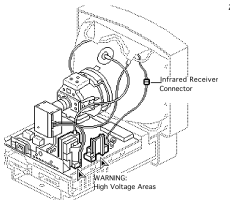
The infrared receiver connector. Apple Computer, Macintosh TV Service Source. Disconnect the infrared receiver connector.[1]
Connectors BP2 and BD1 and the cable retainer (LC 520/550/575 Service Source drawing, the same in the TV manual). Apple Computer. Release the latch on BP2 with a small screwdriver and disconnect the degauss cable.[1]
Pulling the CRT board assembly straight off the neck of the tube (LC 520/550/575 Service Source drawing, the same in the TV manual). Apple Computer. Pull the CRT board assembly straight off the neck of the CRT, without twisting or bending it.[1]
If you are fitting a replacement, move the cable retainer from the old board to the new one.[1]
Refit in the reverse order: slide the board in, push the CRT board straight on to the neck of the tube, refit the anode cap, reconnect BD1, BP2, the infrared receiver connector and the two degauss panel ground cables, and route the wires through the cable retainer.[1]
Switch on and check for the start-up chime and a picture.[4]
Apple requires the cutoff adjustment whenever the analog board or the CRT is replaced, followed by white balance. The procedure is on Macintosh LC 520 Video Adjustment; on the TV, set brightness to midrange from the Brightness control panel.[1][6]
Owners have found the assembly number 630-0355 on the Macintosh TV board as well as on LC 575 and Performa 550 boards, and report fitting LC 5xx analog boards in a Macintosh TV. kefkafloyd notes that the LC 520, 550 and 575 boards do not have the resistor at the AC connector.[7][3]
↑ 2.02.1Apple Computer, Macintosh TV Service Source, Exploded View (PDF p. 139): Analog Board 661-0872.
↑ 3.03.13.2Apple Computer, Module Identification, part number 072-8124, CPU PCBs, section 1.18.2 "Macintosh TV Analog Board", Apple P/N 661-0872 (November 1993 page): "The Macintosh TV analog board has a resistor soldered on the backside of the AC connector. The Macintosh LC 520 does not." Hosted as File:Apple Service Module Identification Manual (June 1994).pdf; the page was also posted by kefkafloyd in the TinkerDifferent thread cited below.
↑ 4.04.14.2Apple Computer, Macintosh TV Service Source, Troubleshooting, Symptom Charts pp. 2-17 (PDF pp. 17-32).
↑Apple Computer, Macintosh TV Service Source, Adjustments pp. 1-38 (PDF pp. 100-137): raster height 7 in, width 9 1/4 in, sub-contrast 33 foot-lamberts, the same controls as the LC 520/550/575; brightness is set from the Brightness control panel.
↑Apple Computer, Macintosh TV Service Source, Adjustments, Video pp. 10-12 (PDF pp. 109-111).
↑TinkerDifferent, "Mac LC 575 Analog Board recap guide photos": dougg3, 2 August 2025 (Macintosh TV board 630-0355, recapped in 2013); kefkafloyd, 6 May 2026 (Module Identification page; resistor visible in dougg3's photo; LC 5xx boards used in a Macintosh TV).